Staying Safe during Resistance Welding

Resistance welding (RW)

To see this article please enter to AWS, this article belongs to AWS :

https://www.aws.org/magazines-and-media/magazine-and-journal/welding-digest/welding-digest-staying-safe-during-resistance-welding/

Resistance welding (RW) is a thermo-electric welding process in which the weld is made by a combination of pressure and current. The process involves the joining of metals by applying controlled pressure and passing current through the metal area to be joined. There are several different forms of RW (e.g., spot, seam, projection, single-sided, bonding, cross wire, micro, flash, and upset welding) that differ primarily by the types and shapes of weld electrodes used to apply the pressure and conduct the current.

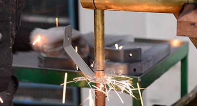
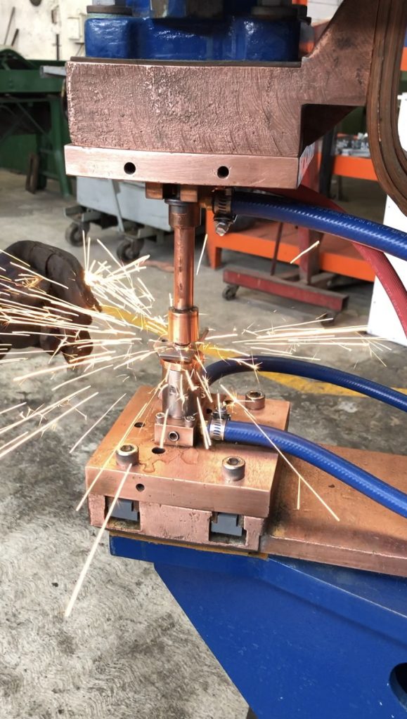
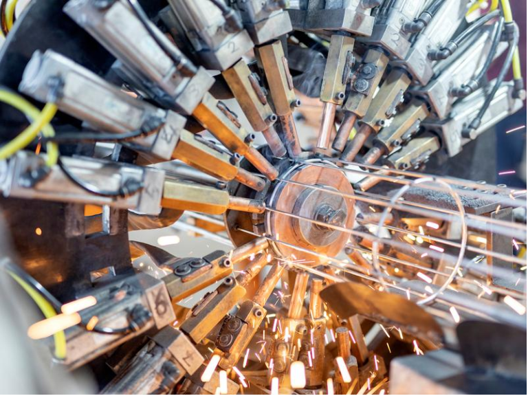
Photo: Resistance welding is a thermo-electric process in which heat is generated at the interface of the parts to be joined by passing an electrical current through the parts. There are several different processes of resistance welding, including spot welding.

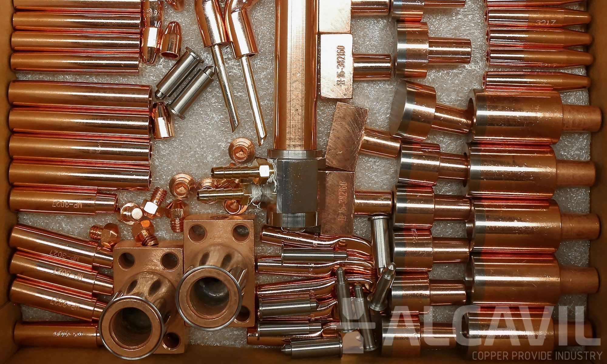
The electrodes, typically manufactured from copper-based alloys due to their superior conductive properties, are cooled by water flowing through cavities inside the electrode and the other conductive tooling of the RW machine.

There are several key advantages of the RW process, including the following:

-Very short process times;

-No consumables, such as brazing materials, shielding gas, solder, or welding rods/wires;

-Operator safety because of low voltage and fume emission;

-Cleanliness and environmentally friendliness; and

-Formation of a reliable electro-mechanical joint.

Safety Hazards

RW is not an open-arc process, and the weld is made inside or between the workpieces. As a result, several unique hazards must be considered during RW:

-Flying sparks can cause fire and explosion.

-Flying sparks and spatter can burn or injure eyes and skin.

-Electric shock can occur from live electrical parts.

-Hot metal and parts can cause burns.

-Moving electrode parts, such as tongs, tips, and linkages, can injure fingers and hands.

-Spot welding parts coated with cleaners, paints, or platings can create fumes.

How to Avoid the Hazards

The following lists several ways to stay safe during RW:

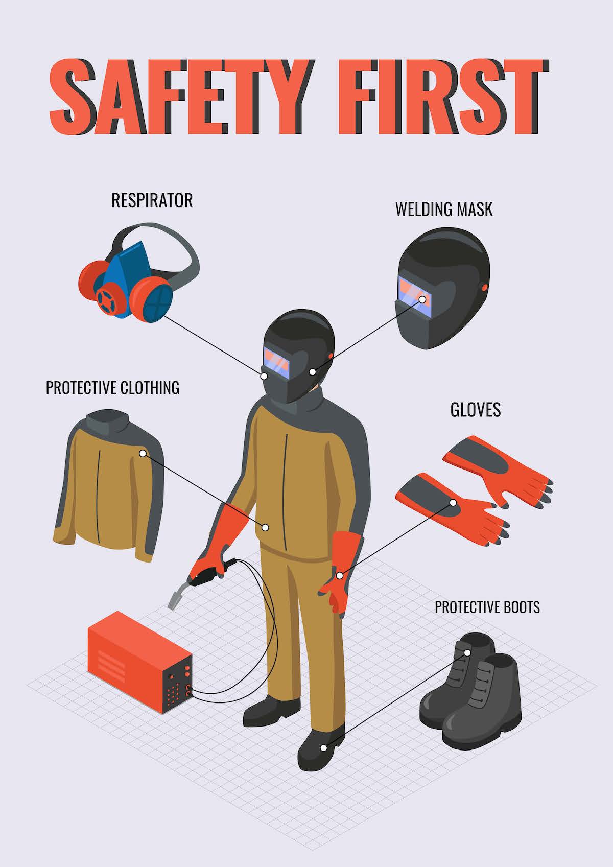
-Wear the appropriate personal protective equipment, including safety goggles or a face shield/safety glass; long-sleeved shirts made from nonmelting material; and dry, insulated gloves.

Staefty First
Staefty First

-Do not weld near flammables (move flammables away from the welding area). Also, keep a fire extinguisher nearby and know how to use it.

-Do not breathe the fumes. Use adequate ventilation and read safety data sheets for metals, coatings, and cleaners.

-Do not put your hands between tips. Keep away from linkages and pinch points. Keep all guards and panels in place.

-Do not touch hot workpieces, tips, or tongs with your bare hands. Allow tongs and tips to cool before touching. Wear proper insulating gloves when handling hot work or parts.

-Install and ground the unit according to electrical codes. Grounding should be provided to the secondary of all welding transformers for multispot, projection, and seam welding machines.

-Disconnect the input power before servicing. Ensure all equipment, with an appropriate safety disconnecting switch or circuit breaker, has been installed by qualified electricians.

-A thermal protection switch should be provided for ignition tubes used in RW equipment.

-Keep guards in place to mitigate activation of all automatic or air and hydraulic clamps, including foot pedals/switches.

-Use complete enclosures to insulate and protect stored energy or capacitor discharge types of RW equipment and control panels involving high voltage, including door interlocks that interrupt power and discharge capacitors.

-Use electronic eye, two-hand controls, or protection similar to punch press operation as guarding for all press welding machine operations when there is a possibility of the operator’s fingers being under the point of operation.

Adapted from American Welding Society (AWS) Safety and Health Fact Sheet No. 21, Resistance Welding. All of the AWS Safety and Health Fact Sheets are available through the AWS website at aws.org. Click on Standards on the home page and then on Safety & Health. AWS disclaims liability for any injury to persons or property, or other damages of any nature whatsoever, whether special, indirect, consequential or compensatory, directly or indirectly resulting from the publication, use of, or reliance on this information. AWS also makes no guaranty or warranty as to the accuracy or completeness of any information published herein.https://www.aws.org/magazines-and-media/magazine-and-journal/welding-digest/welding-digest-staying-safe-during-resistance-welding/

Soldadura por puntos

Soldadura por puntos

El uso principal de la soldadura por puntos de resistencia es unir láminas de metal superpuestas cuando la unión no tiene que ser hermética a los gases o líquidos.

La fabricación mediante este proceso es económica y rápida ya que no se requieren sujetadores separados.
Aunque la producción comercial de conjuntos se limita generalmente a espesores de hoja de hasta aproximadamente 0,125 pulgadas, se pueden unir placas de hasta 0,25 pulgadas o más.

La soldadura por puntos se utiliza para la fabricación de muchos productos de chapa metálica, como electrodomésticos, carrocerías de automóviles, cerramientos y muebles. El proceso se puede automatizar fácilmente y una variedad de máquinas de soldadura por resistencia están disponibles de varias fuentes. La mayoría de los metales se pueden soldar por resistencia si se utiliza el equipo requerido y se siguen los programas de soldadura adecuados.

Protección para operarios de Punteadoras

Protección para operarios de Punteadoras

Operator Protection

Muchas compañías desconocen que hay una manera de proteger a el operario. El 90% de los accidentes ocurren durante la alineación de los electrodos. Es debido a esta necesidad de proteger a los operarios, que el Ingeniero Estadounidense, Roger Hirsch de Unitrol Electrodos, creo un sistema que al detectar otro material que no sea metal, ocasiona que la presión baje de tal grado que no lastimaría en cierto momento las extremidades del operador, avalado por OSHA. Sistema del cual Alcavil S.A. DE C.V. es distribuidor (incluye instalación). Este sistema también se utiliza para punzonadoras neumáticas.

Operator Protection

Soldadura por Proyecciones México

Projection Welding Mexico


In the regular sheet to sheet welding we saw how size and shape of the weding electrodes was of great importance in determining the size, strength and quality of the Weld. It was also noted that all of the welding current is concentrated in the electrode tip. This current is in the order of thousands of amperes per square inch.

Therefore, electrode strength or hardness is sometimes scarified in or/ mushrooming.

Projection welding is a resistance process by which the current and heating during welding are localized at a predetermined point by the design of the parts being welded. This is usually accomplished by a projection, or embossment, on one or both of the work pieces.

It can readily be seen that the size of the electrode tip has no bearing in projection welding and that the current density may be considerably reduced, permitting the use of harder and tougher electrode material.

A projection may be embossed in a sheet of metal, it may be produced on a solid piece of metal by machining, or produced on the edge in a punch press in any of several ways. The height may be anywhere from a few thousandths of an inch to 0.125-in or more depending on the thickness of the material to be welded. The purpose of projections is to concentrate the current and force at predetermined points. In this modification of the spot welding process the concentration of the welding current is determined by the preparation of the workpiece rather than by the size or shape of the electrode.

There are several advantages to be gained by the use of projection, namely:

  • Ease of obtaining satisfactory heat balance for welding difficult combinations.
  • More uniform results in many applications.
  • Increased output per machine because of making several welds simultaneously.
  • Longer electrode life
  • Welds may be placed more closely together.
  • Parts are more easily welded in a assembly fixture.
  • Finish, or surface appearance, is often improved.
  • Parts may be projection welded that could not be otherwise resistance welded.


The advantages will be discussed as numbered:

  1. The major portions of the heat tends to develop in the part bearing the projections during the welding operation. Weldments composed of thickness ratios of 4 (or more) to 1 are sometimes difficult to spot weld. The flexibility of selecting the projection size and its location allow ratios of 6 (or more) to 1 to be readily projection welded. For this reason the projections should be produced on the heavier of the two pieces of the same metal or, if possible, on the piece of higher conductivity if dissimilar metals are being joined. The reverse can, however, be used under some conditions.
  2. Uniform projections may be readily obtained on a punch press. The effect of variables such as contact area between the parts and electrode mushrooming are reduced. The surface condition of the parts has less effect than in spot welding. If a part requires several welds, they can be made simultaneously, thus avoiding difficulties due the shunt currents. Both the location and strength of the resulting welds are more reliable.
  3. The only limits to the number of welds that can be simultaneously made seems to be the ability to control force and current so they are equally divided between the welds, and the capacity if the equipment. It is much easier to achieve the proper division of force and current with projections than with flat surfaces. When several welds, approximately six or eight are needed, they are usually made simultaneously.
  4. In many cases, the areas to be joined are flat except for the projections. In such cases the electrodes are flat and large enough to contact a large area. In other cases, when the surface to be contacted is irregular in shape, the electrode is fitted to the surface so that a night force may be applied without distortion the part. A large current may be introduced without damaging the surface. Electrodes with large contact surface show little wear and consequently require less attention or maintained.
  5. If two spot welds are located too closely together, current from the second weld is shunted though the preceding weld. Since projection welds are made simultaneously, there is less trouble due to shunting. However, if they are placed to closely together irregularities in forming the projections may lead to poor distribution of the current. The only limitations on the arrangement or spacing of projections are the ease of equalizing the distribution of force and current and the size of the machine. If, however, more than three projections are welded simultaneously, the height of the projections must be uniform within close limits, to avoid having some of the projections fused before other have made contact. Multiple-impulse welding or the use of upslope may be help in this case.


For more information, you can contact us directly to our email or check AWS Resistance Welding Manual


Proyección Soldadura México


En la soldadura normal de lamina-lamina, vimos cómo el tamaño y la forma de los electrodos de ondulación eran de gran importancia para determinar el tamaño, la resistencia y la calidad de la soldadura. También se observó que toda la corriente de soldadura se concentra en la punta del electrodo. Esta corriente es del orden de miles de amperios por pulgada cuadrada.

Por lo tanto, la fuerza o la dureza del electrodo a veces se escarifica o se deforma.

La soldadura por proyección es un proceso de resistencia mediante el cual la corriente y el calentamiento durante la soldadura se localizan en un punto predeterminado mediante el diseño de las piezas que se sueldan. Esto generalmente se logra mediante una proyección, o repujado, en una o ambas piezas.

Se puede ver fácilmente que el tamaño de la punta del electrodo no tiene huella en la soldadura de proyección y que la densidad de corriente puede reducirse considerablemente, permitiendo el uso de material de electrodo más duro como Cobre Clase 2, o en casos para aumentar duración se utiliza cobre tungsteno.

Una proyección puede marcarse en relieve en una lámina de metal, puede producirse en una pieza sólida de metal mediante maquinado, o producirse en el borde en una punzonadora de cualquiera de varias maneras. La altura puede ser desde unas pocas milésimas de pulgada hasta 0.125 pulgadas o más, dependiendo del grosor del material a soldar. El propósito de las proyecciones es concentrar la corriente y la fuerza en puntos predeterminados. En esta modificación del proceso de soldadura por puntos, la concentración de la corriente de soldadura se determina por la preparación de la pieza de trabajo en lugar de por el tamaño o la forma del electrodo.

Se pueden obtener varias ventajas con el uso de la proyección, a saber:

1- Facilidad de obtener un balance de calor satisfactorio para combinaciones difíciles de soldar.

2- Resultados más uniformes en muchas aplicaciones.

3- Incremento de la producción por máquina debido a que se realizan varias soldaduras simultáneamente.

4- Mayor vida útil del electrodo.

5- Las soldaduras se pueden colocar más juntas.

6- Las piezas se sueldan más fácilmente en un accesorio de montaje.

7- El acabado, o la apariencia de la superficie, a menudo se mejora.

8- Las piezas pueden estar soldadas por proyección que de otra manera no podrían soldarse por resistencia.


Las ventajas serán discutidas como numeradas:

  1. Las partes principales del calor tienden a desarrollarse en la parte que lleva las proyecciones durante la operación de soldadura. Las soldaduras compuestas por relaciones de grosor de 4 (o más) a 1 a veces son difíciles de puntear. La flexibilidad de seleccionar el tamaño de proyección y su ubicación permiten que las relaciones de 6 (o más) a 1 sean fácilmente soldadas por proyección. Por esta razón, las proyecciones deben producirse en la más pesada de las dos piezas del mismo metal o, si es posible, en la pieza de mayor conductividad si se están uniendo metales diferentes. El reverso puede, sin embargo, ser usado bajo ciertas condiciones.


  1. Las proyecciones uniformes se pueden obtener fácilmente en una punzonadora. El efecto de variables como el área de contacto entre las partes y la proliferación de electrodos se reducen. El estado de la superficie de las piezas tiene menos efecto que en la soldadura por puntos. Si una pieza requiere varias soldaduras, se pueden hacer simultáneamente, evitando así dificultades debido a las corrientes de derivación. Tanto la ubicación como la resistencia de las soldaduras resultantes son más confiables.
  2. Los únicos límites al número de soldaduras que pueden realizarse simultáneamente parecen ser la capacidad de controlar la fuerza y ​​la corriente para que se dividan en partes iguales entre las soldaduras y la capacidad del equipo. Es mucho más fácil lograr la división adecuada de fuerza y ​​corriente con proyecciones que con superficies planas. Cuando se necesitan varias soldaduras, aproximadamente seis u ocho, generalmente se hacen simultáneamente.
  3. En muchos casos, las áreas a unir son planas a excepción de las proyecciones. En tales casos, los electrodos son planos y lo suficientemente grandes como para entrar en contacto con un área grande. En otros casos, cuando la superficie a contactar tiene una forma irregular, el electrodo se ajusta a la superficie para que se pueda aplicar una fuerza nocturna sin distorsionar la parte. Se puede introducir una gran corriente sin dañar la superficie. Los electrodos con gran superficie de contacto muestran poco desgaste y, por lo tanto, requieren menos atención o mantenimiento.
  4. Si dos soldaduras por puntos están ubicadas demasiado cerca, la corriente de la segunda soldadura se desvía a través de la soldadura anterior. Dado que las soldaduras de proyección se hacen simultáneamente, hay menos problemas debido a la derivación. Sin embargo, si se colocan muy cerca de las irregularidades en la formación de las proyecciones, esto puede llevar a una mala distribución de la corriente. Las únicas limitaciones en la disposición o el espaciado de las proyecciones son la facilidad de igualar la distribución de fuerza y ​​corriente y el tamaño de la máquina. Sin embargo, si se sueldan más de tres proyecciones simultáneamente, la altura de las proyecciones debe ser uniforme dentro de límites cercanos, para evitar que se fusionen algunas de las proyecciones antes de que otras hayan hecho contacto. La soldadura por impulsos múltiples o el uso de pendientes ascendentes pueden ser de ayuda en este caso.


Para obtener más información, puede contactarnos directamente a nuestro correo electrónico o consultar el Manual de soldadura por resistencia de AWS